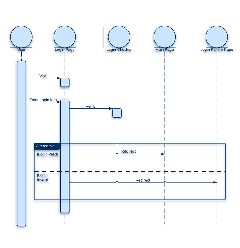

In order to construct a system sequence diagram, you need to be familiar with the unified modeling language (UML).

The purpose is to illustrate the use case in a visual format. These tasks may include repetitive, simple, or complex tasks. Professionals, in developing a project, often use system sequence diagrams to illustrate how certain tasks are done between users and the system. Indication of any loops or iteration area.Return values (if any) associated with previous messages.Messages (methods) invoked by these actors.

This allows the specification of simple runtime scenarios in a graphical manner.Ī system sequence diagram should specify and show the following: A sequence diagram shows, as parallel vertical lines ( lifelines), different processes or objects that live simultaneously, and, as horizontal arrows, the messages exchanged between them, in the order in which they occur.


 0 kommentar(er)
